Outcome
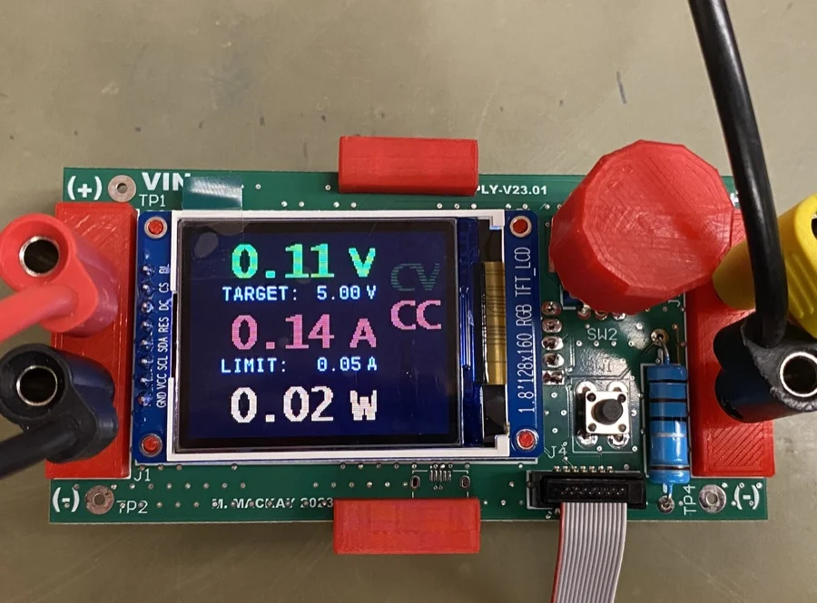
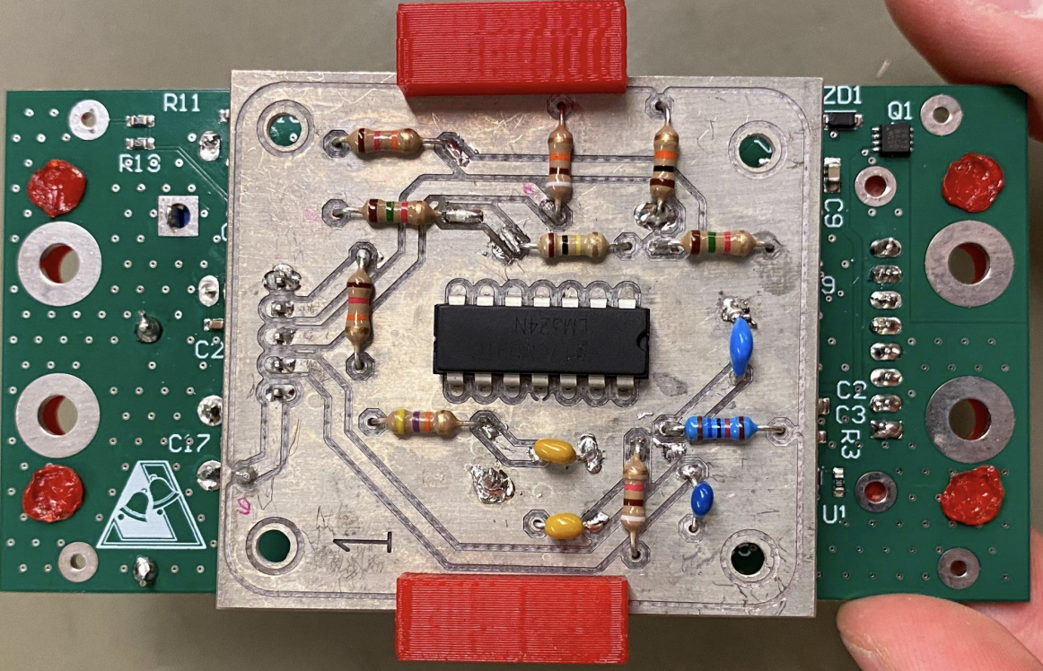
We assembled a working supply with constant-voltage and constant-current modes, then compared its display readings with a multimeter. The current-sensing PCB was designed, soldered, tested, and integrated into the supply.
- Voltage checks covered approximately 1–15 V. Display readings were 0.04–0.11 V above the multimeter readings at the five recorded points.
- Current checks covered setpoints from 0.05–2.5 A, with a maximum display-to-multimeter difference of 0.06 A.
- The current display fluctuated at setpoints below 0.25 A; the report otherwise describes steady operation in current-control mode.
Current-sensing circuit
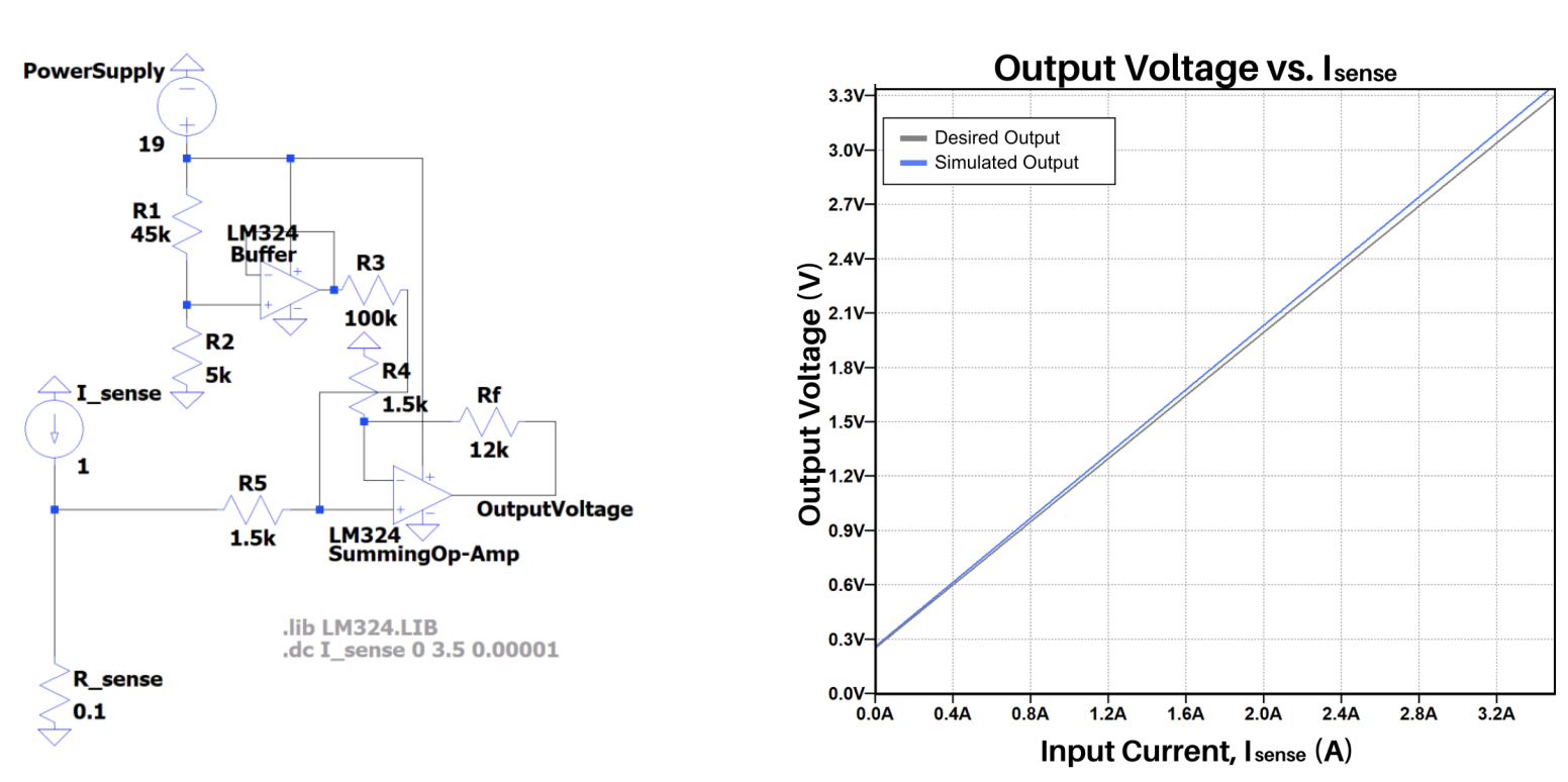
The design target was to convert a 0–0.35 V sense signal into a 0.25–3.30 V output. Our first concept amplified the signal before adding an offset, but the LM324’s low-output limitation caused problems near zero input. We instead combined the sense signal with a buffered reference before amplification and checked the design in LTSpice.
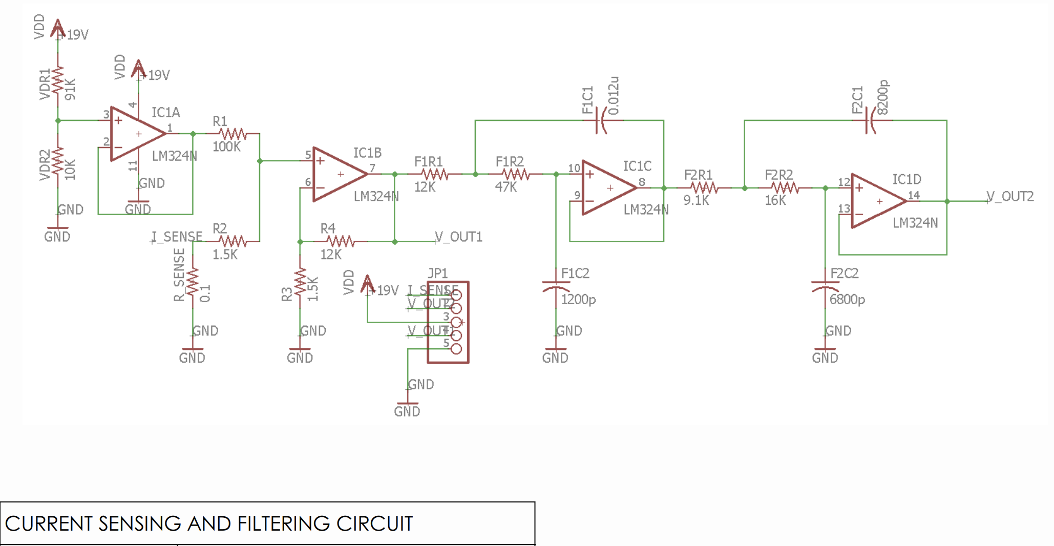
The final schematic includes two active low-pass filter stages after the amplifier. We selected standard component values and assessed the effect of resistor tolerances.
PCB layout and assembly
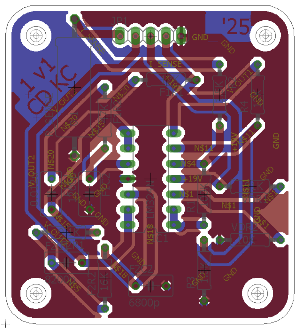
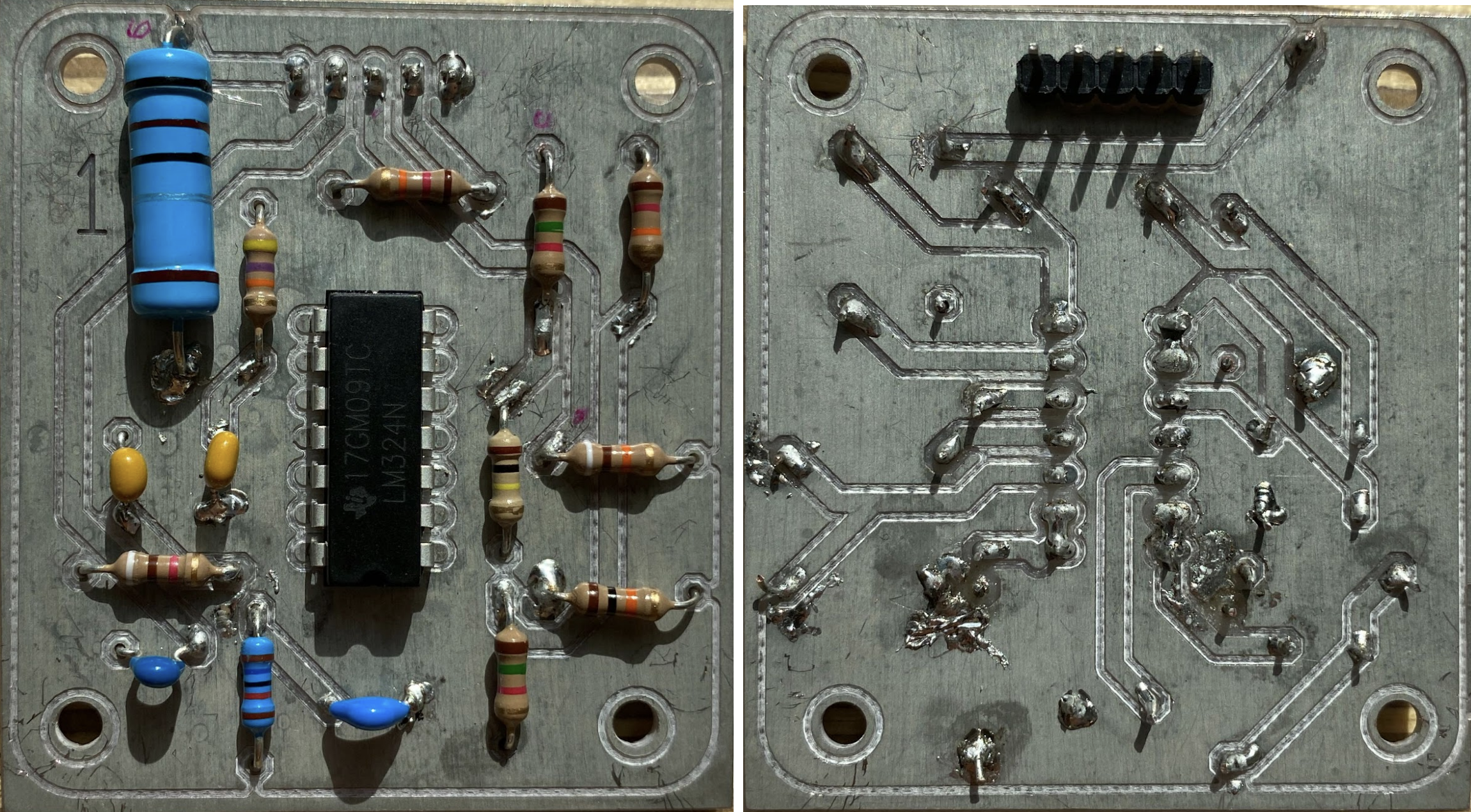
I routed the two-layer board in EAGLE without vias and added grounded copper pours on both layers. The build initially produced an abnormally high output because of an unintended ground connection at the buffer output. I identified and corrected the connection during debugging.
Final supply checks
| Mode | Display reading | Multimeter reading |
|---|---|---|
| Voltage | 1.11 V | 1.00 V |
| Voltage | 9.12 V | 9.06 V |
| Voltage | 15.16 V | 15.12 V |
| Current | 0.05 A | 0.04 A |
| Current | 1.50 A | 1.56 A |
| Current | 2.50 A | 2.50 A |
Selected measurements from the assembled power supply. These are point checks, rather than an accuracy specification across the full operating range.